

Week 4
Week 4 Description:
Week 4
Electronics Production
Assignment: Make an in-circuit programmer by milling the PCB
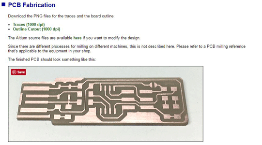
PCB Fabrication:
I used the tutorial off of Fab Academy week 4 schedule (Brian)
- Find the tutorial
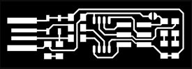
- Download Traces (PNG) & Outline Cutout (PNG)
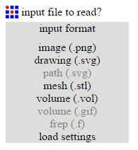
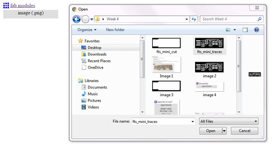
- Go to fabmodules.org
- Input Format (image (PNG))
- Find traced (fts_mini_traces.png) file (repeat for outline)
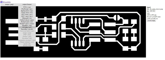
- Output format
- G-Code
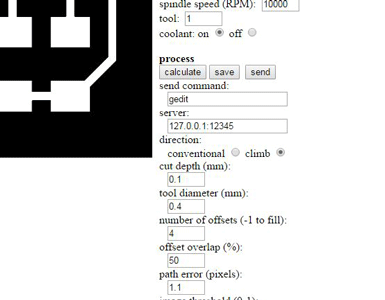
- Process
- PCB 1/64” – Outline 1/32”
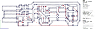
- Calculate
- Save the file on a flash drive for Path Pilot


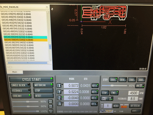
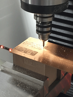
We have a separate station set up for our CNC Mill. On that computer I opened the file in Path Pilot.
- Open traces file
- Home the X Y & Z
- Level the surface you will be milling on
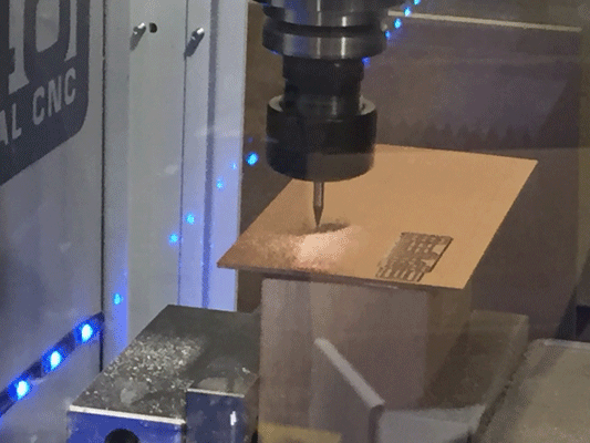
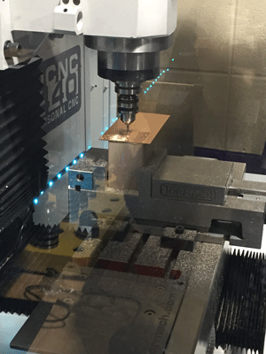
- Tape down with double sided tape the FR1
- Find a point on FR1 to use as a starting point for the file
- Find X & Y first
- Touch down with Z
- Zero out all on Path Pilot
- Press start cycle button
- Open Outline file
- Use pad to take X & Y to zero
- Take Z to touch down (different length because of the 1/32” bit)
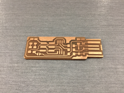
- Once the piece was finished milling I used a sharp metal edge to deburr it and then washed it with soap and water.
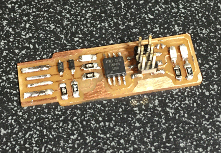
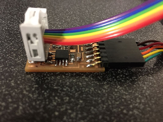
Soldering:
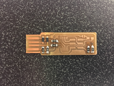
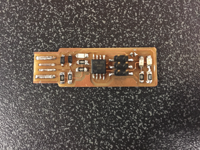
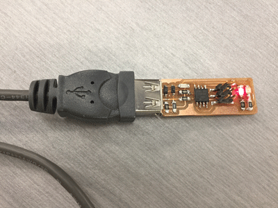
When the parts came in I saw that they were tiny! The tip of the soldering iron needed to be changed and we didn’t have one very small so this was going to be a challenge. Once I heated up the iron I made sure to heat both the copper and the component I was soldering by holding the tip to connect both. Then I quickly touched the solder (that included flux in it) to the soldering iron tip. The solder became shiny and connected the two things together. I have a lot of experience in soldering in terms of jewelry and small metals work. I have never used a soldering iron, but I think it worked relatively well once I got going. I follow the chart that was provided and made sure that all of the components were in the right direction and place on the board. Once finished I used a USB extender and plugged it into a computer. I heard the noise it makes when I usually plug something into a USB port and my red LED light illuminated! Success?!
Flashing the board:
I downloaded the following files from link provided: http://fab.cba.mit.edu/classes/863.16/doc/projects/ftsmin/index.html
Then I downloaded fts_firmware_bdm_v1
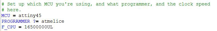
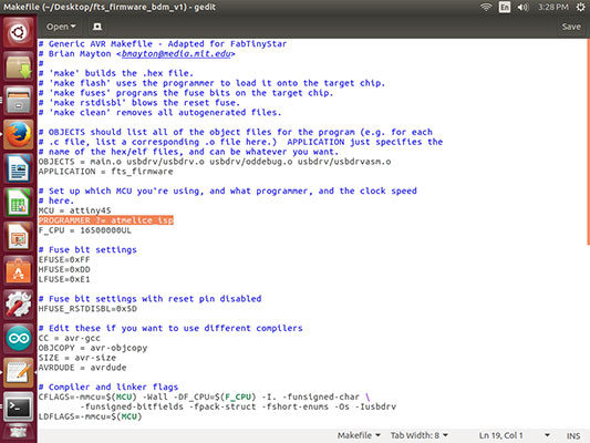
Unzipped the files and changed the make file to read atmel_ice instead of usbtiny.
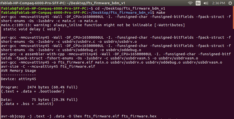
I then cd'd into the folder where I had saved the make file as seen below.
 At this time I ran into a road block. I tried everything. I checked the solder, the board traces, the parts on the board to make sure they were correct and on the correct direction. Everytime I went to do the make flash command I got the following message:
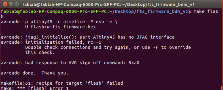
Finally I decided that I should swap out the attiny45 that I had on the board for a new one in case something was wrong with the actual microcontroller. After place the new microcontroller and changing out the ceramic capacitor (I am not sure what I had used the first time, maybe a pF capacitor, but I needed to put on a .1 uF capacitor) I made the attempt to reflash the board. I checked the make file before I did this as well.
In the make file I needed to use a different work for the Atmel Ice (my avr). I was using atmelice from one of the tutorials I had found and realized that through my work in Fab Academy I really needed to use atmelice_isp.
I then made the change for the isp and went through the commands from the begining. This time with success!!
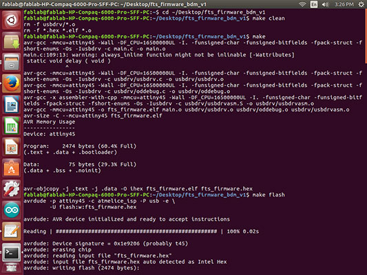
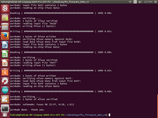
The next commands were as follows:
1. cd'd into where the folder was
2. make clean (I only did this to make sure any previous attempts were not going to interfere).
3. make (before you do this step make sure that you have changed the make file you are using to reflect the programmer that is hooked up to your FabISP)
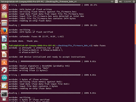
4. make flash (This will program the memory with the hex file created by the make file)
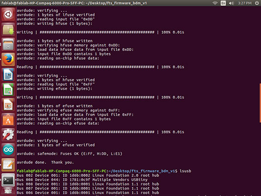
5. make fuses (This step sets up all of the fuses minus the pin that disables the reset)
6. At this point you will need to unplug everything and only plug back in your board to the extention usb.
7. lsusb (This command will list the USB devices to check if it is being recognized.)
8. If it worked, it will show something similar to a "Multiple Vendor" option.
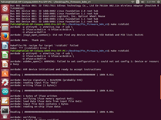
9. Then plug the FabISP back into the AVR (Atmel Ice in my case)
10. make rstdisbl (This command will include the reset disable part)
11. Then deconnect the solder joint from the VCC to the Vprog pin. This will make it into your own programmer!
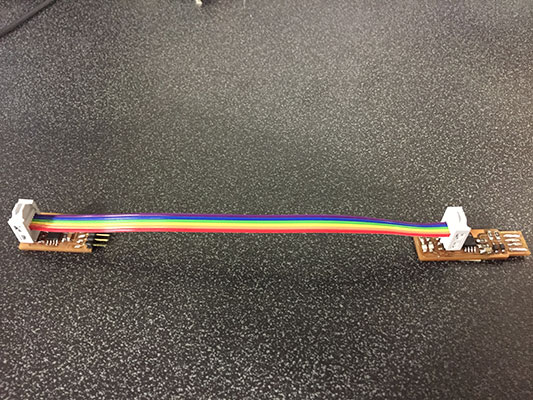
Now to try to program something else with it! I made a 6 wire ribbon cable connector.
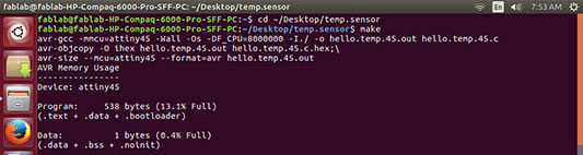
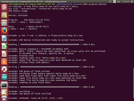
I got out my temp.sensor from the input week and I looked at the makefile to make sure it included the program-usbtiny line:
program-usbtiny: $(PROJECT).hex
avrdude -p t45 -P usb -c usbtiny -U flash:w:$(PROJECT).c.hex
Then I opened the hello.temp.45.c and changed back the char_delay() _delay_ms(100) so I could see a change in the actual board to make sure it worked.
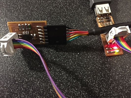
Hooked everything up.
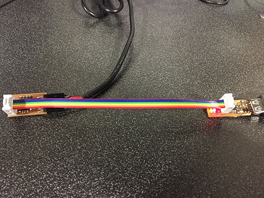
The usbtiny to the usb extention.
Then the ribbon cable from the 6 pin header on the usbtiny to the 6 pin header on the temp sensor making sure to face it the right direction. And then the FTDI to the temp sensor.
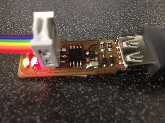
Here you can see the red and the green led on as you would with my Atmel Ice! (very exciting).
After I cd'd into the folder where my makefile for the temp.sensor was, I ran the following commands:
make
make program-usbtiny
Just to be sure I pulled up my python file and it ran much faster then it did before taking the temp.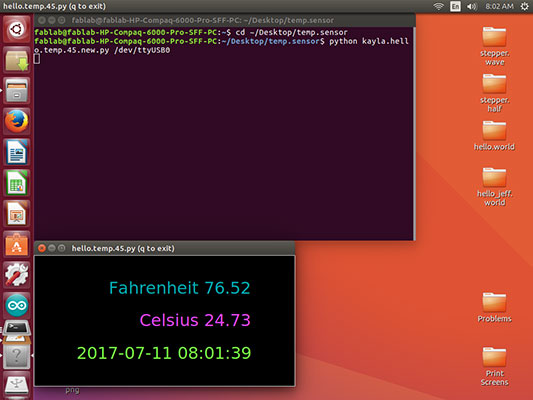
Week 4 Photos